

The P10 or B204 error on Canon G series printers is a common issue. The P10 error means there is a problem with the printer’s hardware. This is similar to problems in older Canon models like the IP2770 and MP278. Fixing this issue can be difficult and expensive. Some technicians try to fix it by changing parts in the mainboard or the main machine.
Before replacing or repairing the mainboard, you can try these steps to fix the P10 error:
Turn off the printer for 5 minutes, then turn it back on.
Check if there are any foreign objects in the printer’s paper tray or output tray. Clean them if necessary.
Reset the waste ink pad counter.
Check the printer cartridge to make sure it’s not damaged. Replace it if needed.
Check the Power Supply Unit (PSU) to ensure it’s working. Replace it if damaged.
Make sure all cables are connected properly and securely.
If none of these steps fix the P10 error, it likely means the mainboard is damaged. The mainboard will need to be repaired or replaced.

There are two ways to fix the mainboard with the P10 error. One is to replace the entire mainboard with a new one, and the other is to replace only the damaged components on the mainboard. Replacing individual parts is usually much cheaper.
Here are the steps to repair the Canon G Series printer mainboard if you're dealing with the P10 error:
- Remove the plastic bottom PCB cover to access the mainboard.
- Locate 3 resistors connected in series, which are linked to another resistor that forms a voltage divider.

From here, you can continue diagnosing or replacing the damaged components. Replacing just the faulty resistors might fix the issue without the need for a full mainboard replacement.
Here’s how to fix the Canon G Series mainboard with the P10 error step-by-step:
-
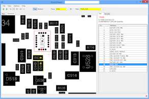
First image: It shows the location of the divider resistor that powers the P-channel MOSFET.
-
Second image:
The yellow box highlights three resistors connected in series. These resistors are linked to the KIC microcontroller pin and the P-channel MOSFET gate pin. These resistors are 8K Ohm.The red box shows the divider resistor connected to B+ and the P-channel MOSFET gate pin. This resistor should be in the range of 10K Ohm to 30K Ohm.
-
Check all four resistors: If any of them is the wrong size, replace it with a new one that matches the correct value.
-
Reassemble the mainboard: After replacing any faulty resistors, carefully put the mainboard back into the printer and run a test print to check if the error is resolved.


No comments:
Post a Comment